trackedbot
Hardware Architecture - tracked_bot
Comprehensive engineering documentation for the electrical hardware, controller boards, power distribution, and signal routing of the tracked_bot autonomous tracked robot platform.
📋 Table of Contents
- System Architecture Overview
- Hardware Stack & Core Boards
- Master Unified Pinout & Interconnect Matrix
- Hardware Documentation Sitemap
- Component Datasheets Directory
- Hardware Media & Images
🚀 System Architecture Overview
The tracked_bot platform implements a modular dual-processor computing architecture using the standard Arduino Uno R3 mechanical and electrical footprint:
  +---------------------------------------------------------------------------------------------------+
  |                                   TRACKED_BOT HARDWARE SYSTEM                                     |
  +---------------------------------------------------------------------------------------------------+

     [ Remote Wi-Fi Client ] (PC / Smartphone / ROS Node)
                |
                | IEEE 802.11 b/g/n (UDP/TCP Telemetry & Motion Commands)
                v
  +-----------------------------+---------------------------------------------------------------------+
  | MAIN CONTROLLER BOARD       | TZT Uno WiFi R3                                                     |
  |                             +---------------------------------------------------------------------+
  |   +---------------------+   |   +-----------------------+             +-----------------------+   |
  |   |       CH340G        |   |   |        ESP8266        |             |      ATmega328P       |   |
  |   |    USB-to-UART      |   |   |   Wi-Fi Coprocessor   |             |   Primary MCU Core    |   |
  |   +----------+----------+   |   +-----------+-----------+             +-----------+-----------+   |
  |              |              |               |                                 |                   |
  |              +--------------+-------[ 8-Position DIP Switch ]-----------------+                   |
  |                                   (Serial UART D0/RX, D1/TX)                                      |
  |                                                                                       |           |
  |                             Timer0 Fast PWM (D5/OC0B, D6/OC0A) <----------------------+           |
  |                             74HC595 Shift Bus (D4/CLK, D7/EN, D8/SER, D12/LATCH) <----+           |
  |                             Sensors & ADC Bus (A0..A5, D2/INT0) <---------------------+           |
  +-----------------------------+---------------------------------------------------------|-----------+
                                                                                          |
                                                                                          v
  +-----------------------------+---------------------------------------------------------------------+
  | MOTOR DRIVER SHIELD         | L293D Motor Driver Shield                                           |
  |                             +---------------------------------------------------------------------+
  |   +---------------------+   |   +-----------------------+             +-----------------------+   |
  |   |      74HC595        |   |   |       L293D IC1       |             |       L293D IC2       |   |
  |   | 8-Bit Shift Reg     |======>| Dual H-Bridge Driver  |             | Dual H-Bridge Driver  |   |
  |   | (Dir Demux Q0..Q7)  |   |   | (Channels M1 & M2)    |             | (Channels M3 & M4)    |   |
  |   +---------------------+   |   +-----------------------+             +-----------+-----------+   |
  |                             |                                                     |               |
  +-----------------------------+-----------------------------------------------------|---------------+
                                                                                      |
                                               +--------------------------------------+
                                               | (Left Track M3 & Right Track M4)
                                               v
  +---------------------------------------------------------------------------------------------------+
  | LOCOMOTION PLATFORM         | T101 Aluminum Chassis + Dual DC Geared Motors + Rubber Tracks       |
  +---------------------------------------------------------------------------------------------------+
🧩 Hardware Stack & Core Boards
| Layer | Component | Hardware Model | Function & Role | Detailed Guide |
|---|---|---|---|---|
| Main Board | Hybrid Dual-SoC Controller | Uno+WiFi R3 (ATmega328P + ESP8266) | Dual-processor board (marketed as TZT, RobotDyn, or WeMos Uno WiFi) with ATmega328P (16 MHz) for real-time motion and ESP8266 (80 MHz) for Wi-Fi. | main_board.md |
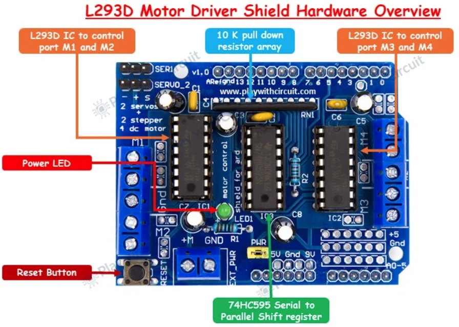
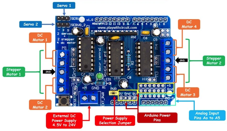
| Motor Driver | Dual Quadruple Half-H Shield | L293D Motor Shield | 2x L293D H-bridges (up to 4 DC motors / 2 steppers) + 74HC595 shift register direction multiplexer. | motor_shield.md |
| Power Distribution | Dual-Supply Rail Architecture | EXT_PWR & USB Rail |
Isolated motor power rail (2S Li-Ion 7.4V–8.4V) and clean MCU logic power (5V USB/power bank). | power_supply.md |
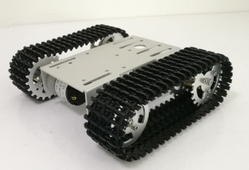
| Locomotion | Tracked Robot Chassis | T101 Platform | Aluminum alloy chassis with suspension wheels, rubber tracks, and dual high-torque DC gearmotors. | body/README.md & body_platform.png |
| Peripherals | Sensors & Telemetry | HC-SR04, MPU-6050, ADC | Ultrasonic obstacle detection, 6-axis IMU gyro/accelerometer on I2C, and battery voltage divider on A0. | main_board.md |
📌 Master Unified Pinout & Interconnect Matrix
This master matrix consolidates all physical signal mappings between the ATmega328P microcontroller, the ESP8266 Wi-Fi coprocessor, and the L293D Motor Driver Shield:
1. Digital I/O Pins (D0 - D13)
| Arduino Pin | AVR Port | AVR Hardware Function | L293D Shield Interconnect | ESP8266 Interconnect | tracked_bot Dedicated Purpose |
|---|---|---|---|---|---|
| D0 | PD0 |
RXD (USART0 Receiver) |
Not connected | Connected via DIP SW1 | Serial In: Receives motion commands from ESP8266 Wi-Fi |
| D1 | PD1 |
TXD (USART0 Transmitter) |
Not connected | Connected via DIP SW2 | Serial Out: Transmits telemetry packets to ESP8266 Wi-Fi |
| D2 | PD2 |
INT0 (External Interrupt 0) |
Not connected | Not connected | FREE GPIO: Low-latency sensor interrupt or wheel encoder |
| D3 | PD3 |
OC2B (Timer2 Output Compare B) |
Motor 2 Speed PWM (PWM2B) |
Not connected | Reserved for Auxiliary Motor 2 |
| D4 | PD4 |
XCK / T0 (General I/O) |
74HC595 Shift Clock (DIR_CLK) |
Not connected | Shift Register Clock: Clocks direction bits into 74HC595 |
| D5 | PD5 |
OC0B (Timer0 Output Compare B) |
Motor 4 Speed PWM (PWM0B) |
Not connected | Right Track Speed PWM: Timer0 Fast PWM (0–255) |
| D6 | PD6 |
OC0A (Timer0 Output Compare A) |
Motor 3 Speed PWM (PWM0A) |
Not connected | Left Track Speed PWM: Timer0 Fast PWM (0–255) |
| D7 | PD7 |
AIN1 (General I/O) |
74HC595 Output Enable (DIR_EN) |
Not connected | Shift Register Output Enable: Active-low output driver |
| D8 | PB0 |
ICP1 / CLKO (General I/O) |
74HC595 Serial Data (DIR_SER) |
Not connected | Shift Register Serial Data: Serial bit-stream input |
| D9 | PB1 |
OC1A (Timer1 Output Compare A) |
Servo 2 PWM (PWM1A) |
Not connected | Reserved for Pan-Tilt Servo 2 |
| D10 | PB2 |
OC1B (Timer1 Output Compare B) |
Servo 1 PWM (PWM1B) |
Not connected | Reserved for Pan-Tilt Servo 1 |
| D11 | PB3 |
OC2A / MOSI |
Motor 1 Speed PWM (PWM2A) |
Not connected | Reserved for Auxiliary Motor 1 |
| D12 | PB4 |
MISO (General I/O) |
74HC595 Latch Clock (DIR_LATCH) |
Not connected | Shift Register Latch: Latches internal buffer to outputs |
| D13 | PB5 |
SCK (Onboard LED) |
Not connected (Arduino LED) | Not connected | FREE GPIO: Built-in LED / SPI SCK clock |
2. Analog Input & I2C Pins (A0 - A5 / D14 - D19)
All analog pins pass directly through the L293D shield to the top breakout pads without electrical interference:
| Arduino Pin | AVR Port | Secondary Hardware Function | System Role in tracked_bot |
|---|---|---|---|
| A0 | PC0 |
ADC0 / PCINT8 |
Battery Voltage Sense: 4:1 resistor voltage divider to monitor 2S battery pack |
| A1 | PC1 |
ADC1 / PCINT9 |
Ultrasonic Sensor (HC-SR04): Trigger output pulse pin |
| A2 | PC2 |
ADC2 / PCINT10 |
Ultrasonic Sensor (HC-SR04): Echo input pulse measurement pin |
| A3 | PC3 |
ADC3 / PCINT11 |
Auxiliary GPIO / Analog Input (free for infrared or bumper switches) |
| A4 | PC4 |
ADC4 / SDA (I2C Data) |
I2C Bus SDA: Connected to MPU-6050 6-DOF IMU gyroscope/accelerometer |
| A5 | PC5 |
ADC5 / SCL (I2C Clock) |
I2C Bus SCL: Connected to MPU-6050 6-DOF IMU gyroscope/accelerometer |
3. Power Supply and Ground Terminals
| Terminal / Pin | Rail Voltage | Source / Destination | Functional Role |
|---|---|---|---|
EXT_PWR (+) |
4.5 V – 24 V DC | External Motor Battery (2S Li-Ion / 7.4V) | Powers L293D IC1 & IC2 H-bridge motor drive stages |
EXT_PWR (GND) |
0 V (GND) | Battery Negative Lead | Common ground return for motor current loop |
5V (Header) |
5.0 V DC | Arduino 5V Regulator / USB bus | Powers ATmega328P logic, 74HC595, and servo headers |
3V3 (Header) |
3.3 V DC | Onboard 3.3V LDO Regulator | Dedicated logic supply for ESP8266 Wi-Fi SoC |
GND (Headers) |
0 V (GND) | Shared System Ground Plane | Common reference for all logic, sensors, and peripherals |
VIN (Header) |
7.0 V – 12 V DC | Connected to DC Barrel Jack / EXT_PWR |
Sourced via DC jack; connected to motor rail when PWR jumper is ON |
📖 Hardware Documentation Sitemap
- main_board.md: Complete specifications for the TZT Uno WiFi R3, 8-position DIP switch mode table, serial multiplexing, and firmware flashing workflows.
- motor_shield.md: L293D driver architecture, 74HC595 shift register bit definitions, Timer0 Fast PWM speed control, and DC/stepper/servo connection guides.
- power_supply.md: Power distribution topology, battery chemistry selection, current budgets, inrush spike management, decoupling, and brownout protection.
📂 Component Datasheets Directory
The datasheets/ directory contains original manufacturer engineering documentation:
| Integrated Circuit | Datasheet Link | Key Features & Focus |
|---|---|---|
| Microchip ATmega328P | atmega328p.pdf | 8-bit AVR RISC microcontroller, Timer0/Timer1/Timer2 registers, USART0 hardware. |
| Espressif ESP8266EX | esp8266ex.pdf | 2.4 GHz Wi-Fi SoC, Tensilica L106 32-bit core, UART interface, power management. |
| WCH CH340G | ch340.pdf | USB to Serial UART bridge controller and driver specifications. |
| TI / ST L293 / L293D | l293.pdf | Quadruple high-current half-H drivers, internal flyback clamping diodes, thermal limits. |
| TI SN74HCS595-Q1 | sn74hcs595-q1.pdf | 8-bit serial-in parallel-out shift register with output latches and Schmitt-trigger inputs. |
🖼️ Hardware Media & Images
The images/ directory contains board layout and pinout diagrams:
-
Motor Driver Shield Assembly: images/motor_driver_shield.png
-
Motor Driver Shield Pinout Diagram: images/motor_driver_shield_pinout.png
-
Mechanical Chassis & Track Assembly: body_platform.png