trackedbot
Mechanical Chassis & Platform - tracked_bot
Mechanical system overview, physical chassis specifications, and assembly documentation for the tracked_bot autonomous tracked robot platform.
📋 Table of Contents
- Mechanical System Overview
- Platform Visual Feature Breakdown
- Top Deck & Chassis Geometry Diagram
- T101 Chassis Specifications
- Skid-Steering Kinematics
- Mechanical Documentation & Guides
- Media & Diagrams Index
🚜 Mechanical System Overview
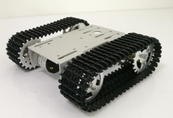
The mechanical locomotion platform of tracked_bot is built upon the T101 Mini Tracked Tank Chassis. Designed for structural rigidity, stability on uneven terrain, and high payload-to-weight ratio, the platform employs a high-grade anodized aluminum alloy chassis driven by two independent DC metal gearmotors coupled to modular continuous caterpillar tracks.
The platform operates via differential skid-steering (tank steering), enabling 360° in-place zero-radius turns by driving opposing tracks in reverse directions, as well as smooth variable-radius turning arcs.
🔍 Platform Visual Feature Breakdown
Referencing the physical platform photograph above (images/body_platform.png), the mechanical architecture consists of seven primary functional sub-assemblies:
  (1) Front Bearing Idler Wheels (Dual Ball Bearings + 5-Screw Hub Flange)
  (2) High-Traction Modular Tracks (Engineering Plastic Links with Inner Guide Lugs)
  (3) Formed 6061 Aluminum Deck & Side Chassis Walls (2.0 mm Anodized Alloy)
  (4) Central Circular Cable Pass-Through Port (Clean Vertical Wiring Harness Route)
  (5) 4x Longitudinal Accessory Mounting Slots (Sliding Brackets & Sensor Mounts)
  (6) Standardized M3 Controller Standoff Pattern (Arduino Uno R3 / Mega Footprint)
  (7) Rear Toothed Drive Sprockets (CNC Aluminum Keyed to Motor D-Shafts)
  (8) Under-Deck 25 mm Metal DC Gearmotors & Protected Battery Bay
1. Monolithic 6061 Aluminum Chassis Body
The main chassis plate is precision-cut and CNC-bent from 2.0 mm thick 6061 sandblasted and anodized aluminum alloy. The downward-folded structural side flanges form an inverted U-channel profile that exhibits exceptional torsional stiffness against skid-steering shear stresses while maintaining an overall chassis weight of only ~530 g.
2. Top Equipment Deck & Mounting Slots
As shown in images/body_platform.png, the upper deck incorporates:
- Central Cable Pass-Through Hole ($\varnothing \approx 18\text{ mm}$): Allows motor power leads, battery cables, and encoder wires to route directly up from the lower equipment bay to the controller shield without exterior hanging wires.
- Four Longitudinal Adjustment Slots ($4 \times 35\text{ mm}$): Permit continuous linear positioning for sensor brackets, camera pan-tilt gimbals, ultrasonic distance sensors, or battery securing straps.
- M3 Mounting Hole Array: Pre-tapped and clearance holes matching the standard Arduino Uno R3 / Mega 2560 standoff pitch ($53.3\text{ mm} \times 27.9\text{ mm}$), ensuring rigid mounting of the Uno+WiFi R3 and L293D motor driver stack.
3. Drive Sprockets vs. Idler Wheels
- Toothed Drive Sprockets (Rear): Machined from solid aluminum with radial weight-reduction cutouts. The outer circumference features positive-engagement gear teeth that mate precisely with the drive windows of the caterpillar track links. Each sprocket hub contains two M3 set-screws (grub screws) that lock onto the flat facet of the motor D-shaft.
- Bearing Idler Wheels (Front): Machined aluminum wheels featuring dual miniature deep-groove ball bearings and a 5-screw outer retaining ring. The idlers maintain track alignment, tension, and provide an elevated obstacle approach angle.
4. Continuous Caterpillar Tracks
The track belts consist of modular, high-durability engineering plastic / POM (polyoxymethylene) interlocking tread links connected with stainless steel hinge pins:
- Outer Surface: Aggressive chevron-patterned anti-skid ribs for high friction on carpet, concrete, tile, and packed dirt.
- Inner Surface: Double-ridge center guide horns that straddle the sprocket teeth and idler wheel rims, preventing track derailment during aggressive in-place skid-steering maneuvers.
5. Lower Equipment & Motor Bay
Located directly beneath the upper aluminum deck, the central chassis cavity encloses:
- Dual 25 mm High-Torque DC Gearmotors: Cylindrical metal gearmotors (visible in images/body_platform.png under the deck edge) secured with four M3 machine screws into the structural side walls.
- Low Center-of-Gravity (CG) Battery Bay: Accommodates a 2S 18650 Li-ion cell holder or 7.4V LiPo battery. Placing the heaviest component below the wheel axle line ensures maximum incline stability and eliminates chassis roll during fast braking.
📐 Top Deck & Chassis Geometry Diagram
The following ASCII schematic illustrates the physical top-down layout and component distribution observed in images/body_platform.png:
                             FRONT (Approach Side)
             [Bearing Idler]                     [Bearing Idler]
           +=======================================================+
           |  |###|      /---------------------------\     |###|   |
           |  |###|     |   (o)   [ Slot 1 ]   [ Slot 2 ]  (o) |###|   |
           |  | T |     |                               |  | T |   |
           |  | R |     |   (o)   Arduino Uno R3 Standoffs  | R |   |
           |  | A |     |                               |  | A |   |
           |  | C |     |         ( O ) Wire Port       |  | C |   |
           |  | K |     |                               |  | K |   |
           |  |   |     |   (o)                         (o) |  |   |
           |  | L |     |         [ Slot 3 ]   [ Slot 4 ] |  | R |   |
           |  | E |     |   (o)                         (o) |  | I |   |
           |  | F |     \-----------------------------/    |  | G |   |
           |  | T |          [DC Gearmotor 1]  [DC Gearmotor 2]   | H |   |
           |  |###|      (Internal Lower Equipment Bay)    |###|   |
           +=======================================================+
             [Drive Sprocket]                    [Drive Sprocket]
                              REAR (Motor Drive Side)
⚙️ T101 Chassis Specifications
| Parameter | Specification | Engineering Details & Observations |
|---|---|---|
| Model | T101 Mini Tracked Platform | Standard desktop-scale autonomous robotics platform |
| Chassis Material | 6061 Aluminum Alloy | 2.0 mm thickness, sandblasted, anti-oxidation anodized |
| Track Material | Engineering Plastic (POM / Nylon) | Modular links linked by stainless steel hinge pins |
| Wheel Material | CNC Machined Aluminum | Anodized finish, dual ball bearings on idlers |
| Overall Dimensions ($L \times W \times H$) | ~190 mm $\times$ 165 mm $\times$ 60 mm | Compact desktop footprint |
| Track Width | ~40 mm | Large contact patch distributing ground pressure |
| Track Gauge ($W$) | ~125 mm | Centerline distance between left and right tracks |
| Ground Contact Length ($L$) | ~110 mm | Effective track surface in ground contact |
| Unladen Weight | ~530 g | Bare chassis including motors, tracks, and wheels |
| Maximum Payload | ~2.0 kg – 3.0 kg | Ample margin for controller, batteries, and sensor payloads |
| Operating Voltage | 6.0 V – 9.0 V DC | Nominal 7.4 V from 2S Li-ion / LiPo pack |
| Ground Clearance | ~18 mm | Minimum underbody clearance over obstacles |
| Locomotion Mode | Differential Skid-Steering | Zero-radius in-place spin ($R = 0$) capability |
🔄 Skid-Steering Kinematics
Differential tracked locomotion relies on differing track velocities ($v_L$ and $v_R$) to effect steering:
          v_L (Left Track)               v_R (Right Track)
                 ^                              ^
                 |                              |
            +----+----+                    +----+----+
            |  TRACK  |                    |  TRACK  |
            |  LEFT   | <---- W = 125 mm ->|  RIGHT  |
            +----+----+                    +----+----+
                 |                              |
                 +--------------+---------------+
                                |
                   Linear Velocity:  v = (v_R + v_L) / 2
                   Angular Velocity: omega = (v_R - v_L) / W
- Straight Forward/Reverse: $v_L = v_R$ (Both tracks driven at equal PWM duty cycles).
- Pivot Turn (One Track Locked): $v_L = 0$ or $v_R = 0$ (Robot pivots around the stationary track; turning radius $R = W/2$).
- Zero-Radius Spin (In-Place Turn): $v_L = -v_R$ (Robot spins about its geometric center with zero turning radius $R = 0$).
- Curved Arc Turn: $v_L \ne v_R$ with both non-zero (Gradual steering arc of radius $R = \frac{W}{2} \cdot \frac{v_R + v_L}{v_R - v_L}$).
[!NOTE] Because skid-steering induces lateral track scrub against the ground, the motor torque demand increases significantly during turning. Ensure the L293D Motor Shield is supplied from a dedicated high-current battery rail (not USB).
📖 Mechanical Documentation & Guides
- assembly_guide.md: Detailed step-by-step mechanical construction manual, covering frame assembly, motor faceplate mounting, sprocket set-screw alignment, track pin sizing and tensioning, and M3 standoff placement.
- Hardware & Electrical Architecture (../hw/): Master electrical interconnect matrix, board schematics, motor shield pin mappings, and power supply design.
- Software Architecture (../sw/): Embedded C motion control algorithms, skid-steering kinematics, slew rate acceleration limiters, and hardware drivers.
🖼️ Media & Diagrams Index
- Platform Assembly Reference Photo: images/body_platform.png