trackedbot
Tracked Bot - Mechanical Assembly Guide
Mechanical construction manual, chassis assembly procedure, track tensioning, and hardware mounting guide for the tracked_bot autonomous mobile platform.
For electrical wiring, power connections, and electronics configuration, refer to the Hardware Documentation (../hw/).
Reference Documentation & Media:
- Chassis Assembly Diagram: images/body_platform.png
- Electrical Hardware Overview: ../hw/README.md
- Power & Wiring Architecture: ../hw/power_supply.md
- Motor Driver Specifications: ../hw/motor_shield.md
📋 Table of Contents
- Mechanical Overview & T101 Specifications
- Bill of Materials (BOM) & Fasteners
- Tools Required
- Step 1: Aluminum Frame & Crossbeam Construction
- Step 2: DC Gearmotor Mechanical Installation
- Step 3: Drive Sprockets, Bearings & Idler Wheels
- Step 4: Caterpillar Track Installation & Tensioning
- Step 5: Upper Deck Standoff Mechanical Placement
- Step 6: Mechanical Inspection & Maintenance
🚜 Mechanical Overview & T101 Specifications
The tracked_bot utilizes an all-metal T101 aluminum tracked chassis designed for high ground clearance, structural rigidity, and all-terrain skid-steering locomotion:
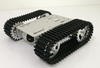
Platform Visual Breakdown (images/body_platform.png):
- (1) Rear Driving Sprockets: Machined aluminum sprockets keyed to the motor D-shafts to transfer torque directly to the tracks.
- (2) Front Idler Wheels: Dual ball-bearing idlers that maintain track alignment, tension, and approach angle for obstacles.
- (3) Continuous Caterpillar Tracks: Modular interlocking links connected via stainless steel pins for high-traction locomotion.
- (4) Side Chassis Panels: 2.0 mm anodized 6061 aluminum alloy walls providing rigid structural support and motor mounting.
- (5) Central Equipment Bay & Upper Deck: Lower cavity houses the battery pack (low center of gravity), while the top plate provides standard Arduino Uno standoff mounting points.
Mechanical Specifications:
| Parameter | Specification | Notes | | :— | :— | :— | | Chassis Model | T101 Mini Tracked Tank Chassis | Modular aluminum construction | | Frame Material | Aluminum Alloy (6061) | 2 mm thickness, sandblasted & anodized | | Track Material | Engineering Plastic / Rubber | Interlocking modular track links | | Overall Dimensions ($L \times W \times H$) | ~190 mm $\times$ 165 mm $\times$ 60 mm | Compact desktop/lab scale | | Chassis Weight | ~530 g (unladen) | Frame, wheels, motors, and tracks | | Max Payload Capacity | ~2.0 kg – 3.0 kg | Dependent on motor torque and surface friction | | Drive Architecture | Dual Independent Track Drive | Differential skid-steering kinematics | | Ground Clearance | ~18 mm | Center underbody clearance |
🔩 Bill of Materials (BOM) & Fasteners
| Component | Quantity | Material / Description | Purpose |
|---|---|---|---|
| Side Structural Panels | 2 | 2 mm Anodized Aluminum | Left and right track mounting chassis walls |
| Central Load Crossbeams | 2 | Aluminum U-channel / Stiffeners | Structural rigidity and deck support |
| Upper Deck Plate | 1 | Pre-drilled Aluminum Plate | Mounting surface for controller and battery |
| DC Gearmotors | 2 | DC Motors with Integrated Gearbox | Independent left and right track power |
| Driving Sprockets | 2 | Machined Aluminum Alloy | Transmit torque from motor D-shafts to tracks |
| Bearing Idler Wheels | 2 – 4 | Aluminum with Dual Ball Bearings | Guide tracks and support vehicle weight |
| Track Assemblies | 2 | Interlocking Track Belts | Ground contact and traction |
| Track Hinge Pins | 2 | Stainless Steel Pins | Track belt closure and sizing |
| M3 Countersunk Screws | 12 | Steel M3 $\times$ 8 mm | Frame crossbeam fastening |
| M3 Machine Screws | 8 | Steel M3 $\times$ 6 mm | Motor faceplate attachment |
| M3 Set-Screws (Grub) | 4 | M3 $\times$ 4 mm Socket Head | Locking sprockets to motor D-shafts |
| M3 Standoffs & Nuts | 4 sets | Brass M3 $\times$ 12 mm Standoffs | Electronics deck elevation and isolation |
🔧 Tools Required
- Precision Phillips screwdriver (size PH0 and PH1)
- 1.5 mm, 2.0 mm, and 2.5 mm Metric Allen / Hex keys
- Small needle-nose pliers (for track pin insertion)
- Caliper or steel ruler (for wheel alignment and track sag check)
- Medium-strength threadlocker (Loctite 242 or equivalent)
🏗️ Step 1: Chassis Orientation & Frame Structure
Referencing the assembled platform photograph (images/body_platform.png):
- Orientation Check:
- Identify the front vs. rear of the chassis: The rear features the transverse mounting points for the two cylindrical DC gearmotors directly driving the rear toothed sprockets, while the front features the bearing idler wheels.
- Orient the top aluminum deck so that the central circular cable pass-through hole ($\varnothing \approx 18\text{ mm}$) is positioned centrally, and the four longitudinal adjustment slots extend forward and backward.
- Frame & Structural Crossbeam Assembly:
- Position the left and right structural aluminum side panels against the center deck/crossbeams.
- Hand-thread the M3 countersunk screws through the side panel clearance holes into the threaded frame members.
- Check chassis squaring using a small square or calipers (diagonal measurements between opposite corners should match within $\le 1.0\text{ mm}$).
- Torque all frame screws evenly in an alternating diagonal pattern to eliminate any twist or torsion in the chassis.
⚙️ Step 2: DC Gearmotor Mechanical Installation
As visible in the platform photo (images/body_platform.png), the cylindrical metal gearmotors sit protected directly beneath the main aluminum deck:
- Motor Orientation:
- Insert each 25 mm DC gearmotor into the lower equipment bay so its output D-shaft protrudes through the side panel clearance bore.
- Orient the motor solder terminals inward toward the chassis center cavity, ensuring the wiring harness cannot contact rotating tracks or sprockets.
- Faceplate Fastening:
- Align the threaded faceplate holes with the chassis mounting pattern.
- Fasten each motor with four M3 $\times$ 6 mm machine screws.
- Apply a small drop of medium-strength threadlocker (e.g., Loctite 242) to each screw to withstand vibration during skid-steering turns.
- Verify that the motor shafts extend outward perpendicular to the side panels.
🔄 Step 3: Drive Sprockets, Bearings & Idler Wheels
Notice in images/body_platform.png the visual distinction between the driving sprockets and the idler wheels:
- Rear Driving Sprockets: Feature machined gear teeth along the outer diameter and circular weight-saving cutouts.
- Front Idler Wheels: Feature a smooth outer guide rim and a 5-screw front hub face securing dual ball bearings.
- Rear Drive Sprockets:
- Slide the toothed aluminum drive sprockets onto the motor output D-shafts.
- Align the threaded hub grub screw hole squarely over the flat facet of the D-shaft.
- Apply threadlocker to the M3 grub set-screws and tighten securely with a 1.5 mm hex key.
- Maintain a 1.0 mm to 1.5 mm clearance gap between the sprocket hub and the aluminum chassis wall to prevent frictional rubbing.
- Front Bearing Idler Wheels:
- Press the dual miniature ball bearings into each idler wheel hub.
- Mount the idler assemblies onto the front chassis support axles using M3 axle bolts and nylon locknuts.
- Tighten the locknuts until all axial play is eliminated, while confirming the idler wheel spins freely without friction.
- Verify co-planar alignment: Sight down the side of the chassis to confirm that the rear drive sprocket and front idler wheel are in the same vertical plane.
⛓️ Step 4: Caterpillar Track Installation & Tensioning
As shown in images/body_platform.png, the robot uses modular black engineering plastic (POM) continuous track belts with external anti-slip traction ribs:
- Track Orientation:
- Position the track belts so the outer chevron tread ridges face forward in the direction of travel for optimal traction.
- Ensure the interior center guide lugs align between the teeth of the drive sprocket and the dual flange of the idler wheel.
- Track Sizing & Hinge Pin Insertion:
- Wrap the track around the drive sprocket, along the bottom contact surface, and over the front idler.
- Adjust the link count (adding or removing links using needle-nose pliers or a pin punch) so the ends meet with moderate tension.
- Insert the stainless steel track hinge pin through the joined link knuckles. Ensure the pin is fully recessed and does not extend past the outer edge of the track.
- Track Sag & Tension Verification:
- Support the chassis off the work surface and measure the track sag along the upper horizontal run:
- Optimal Sag: 5 mm to 8 mm midway between the drive sprocket and front idler.
- Tension Too High ($< 5\text{ mm}$ sag): Strains motor bearings, increases no-load current draw, and overheats the L293D H-bridges.
- Tension Too Low ($> 10\text{ mm}$ sag): Risk of track throwing or tooth skipping during high-torque zero-radius skid spins.
- Support the chassis off the work surface and measure the track sag along the upper horizontal run:
📐 Step 5: Upper Deck Standoff Mechanical Placement
Referencing the top deck features in images/body_platform.png:
- Standoff Installation:
- Thread four M3 $\times$ 12 mm brass hexagonal standoffs into the pre-drilled holes on the upper deck matching the standard Arduino Uno R3 mounting hole pattern ($53.3\text{ mm} \times 27.9\text{ mm}$).
- Fasten each standoff from the underside with an M3 nut and split lock washer.
- Equipment Harness Routing:
- Route the motor power leads and battery cables vertically through the central cable pass-through hole ($\varnothing \approx 18\text{ mm}$).
- Install a rubber grommet or protective edge trim around the hole circumference to prevent wire insulation chafing against aluminum edges.
- Lower Bay Battery Securing:
- Secure the 2S 18650 Li-ion battery holder (or 7.4V LiPo pack) inside the lower chassis cavity using hook-and-loop straps through the bottom chassis slots.
- Placing battery mass low and centered between the tracks ensures a low center of gravity (CG), maximizing climbing stability and braking control.
🔍 Step 6: Mechanical Inspection & Maintenance
Before moving to electrical wiring and firmware deployment, perform this mechanical pre-check:
| Inspection Item | Verification Method | Acceptance Criteria |
|---|---|---|
| Sprocket Set-Screws | Apply rotational torque by hand to drive sprockets | Zero slipping or backlash on motor D-shafts. |
| Idler Wheel Freedom | Spin idler wheels with tracks detached | Spins smoothly without grinding or axial wobble. |
| Track Alignment | Roll the chassis manually along a flat surface | Tracks stay centered on sprockets without walking off. |
| Fastener Rigidity | Inspect all M3 frame screws | Fully seated and torqued; no frame flex under hand pressure. |
| Chassis Squaring | Measure diagonal distances across opposite corners | Difference between diagonals $\le 1.0\text{ mm}$. |
Post-Operation Maintenance:
- Track Cleaning: Clean dust, grit, and debris from track link hinges after outdoor runs to prevent link binding.
- Set-Screw Inspection: Check drive sprocket grub screws periodically, especially after prolonged skid-steering rotation sessions.
[!NOTE] Once mechanical assembly is verified, proceed to the Hardware & Electrical Wiring Guide (../hw/) to complete motor soldering, power distribution, and controller installation.