trackedbot
L293D Motor Driver Shield
Technical hardware documentation and register mapping for the L293D Motor Driver Shield (compatible with Arduino Uno R3 / Mega 2560, based on the Adafruit Motor Shield v1 architecture) used on the tracked_bot platform.
Reference Documentation:
- Arduino Project Hub - L293D Motor Driver Shield with Arduino
- Play With Circuit - L293D Motor Driver Shield Complete Guide
Datasheet References:
- L293 / L293D Quadruple Half-H Drivers Datasheet
- SN74HCS595 8-Bit Shift Register with Output Latches Datasheet
Hardware Images:
- Shield Board: images/motor_driver_shield.png
- Shield Pinout: images/motor_driver_shield_pinout.png
📋 Table of Contents
- Hardware Overview & Architecture
- Electrical & Functional Specifications
- Power Supply Configuration & PWR Jumper
- Complete Arduino Pin Allocation Matrix
- 74HC595 Shift Register Mapping & Protocol
- Speed Control via Hardware PWM (Timer0)
- Tracked Bot Motor Mapping (M3 & M4)
- Servo and Stepper Motor Interfaces
- Hardware Protection, Noise Filtering & Troubleshooting
🔧 Hardware Overview & Architecture
The L293D Motor Driver Shield stacks directly onto an Arduino Uno R3 form-factor board. It integrates two dual H-bridge motor driver ICs and an 8-bit serial-in/parallel-out shift register to drive multiple motors while minimizing the required microcontroller GPIO count:
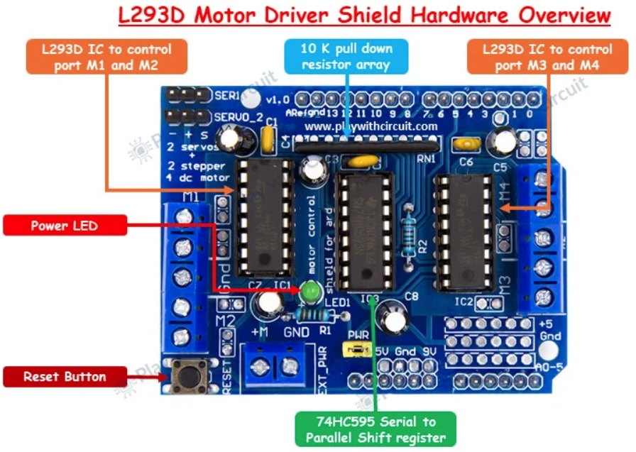
- IC1 (L293D): Quadruple high-current half-H driver. Drives Motor 1 (M1) and Motor 2 (M2).
- IC2 (L293D): Quadruple high-current half-H driver. Drives Motor 3 (M3) and Motor 4 (M4) (dedicated to the left and right tracks on
tracked_bot). - IC3 (SN74HC595N): 8-bit serial-in, parallel-out shift register with output latches. Expands 4 microcontroller control lines into 8 direction signals feeding the H-bridges of IC1 and IC2.
- Pull-Down Resistor Network: A 10 kΩ resistor array grounds the L293D logic inputs during microcontroller power-up and reset cycles, preventing motors from running unpredictably.
- Reset Button: Duplicates the Arduino Uno reset switch to the top of the shield for convenient physical access.
- Power Indicator LED: Illuminates when power is supplied to the motor supply rail.
⚡ Electrical & Functional Specifications
| Parameter | Specification | Notes |
|---|---|---|
| Motor Supply Voltage ($V_{motor}$) | 4.5 V to 24 V DC | Absolute maximum rating up to 36 V per L293D datasheet |
| Logic Supply Voltage ($V_{logic}$) | 5.0 V DC | Supplied directly from Arduino 5 V rail |
| Continuous Output Current | 600 mA (0.6 A) per channel | Depends on ambient temperature and heat dissipation |
| Peak Output Current | 1.2 A per channel | Non-repetitive transient / stall current |
| DC Motor Capacity | Up to 4 bidirectional DC motors | Individual 8-bit speed selection via PWM |
| Stepper Motor Capacity | Up to 2 stepper motors | Unipolar or bipolar (connected to M1–M2 and M3–M4) |
| Servo Motor Capacity | Up to 2 hobby RC servos (5 V) | Dedicated headers with a 100 µF filter capacitor |
| Over-Temperature Protection | Internal thermal shutdown | Disables output stages under excessive junction heat |
| Internal Clamping Diodes | Built-in flyback suppression diodes | Protects against inductive back-EMF spikes |
🔋 Power Supply Configuration & PWR Jumper
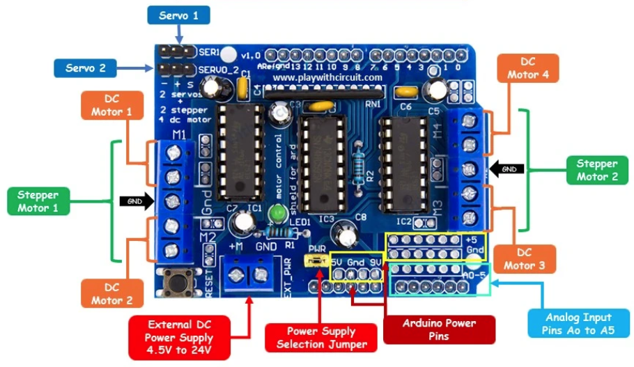
The shield features a 2-pin screw terminal block labeled EXT_PWR and an adjacent 2-pin jumper header labeled PWR (or PWR_JMP).
[!WARNING] Short-Circuit Danger: Never connect an external power source to the
EXT_PWRterminals while thePWRjumper is installed and the Arduino is connected to a computer USB port or DC power jack. Leaving the jumper installed bridges the external motor supply directly to the Arduino’s 5V/VIN rail, which can permanently destroy the Arduino board, the shield, and the host computer’s USB port!
Operating Modes:
| Configuration | PWR Jumper State |
Motor Supply Source | Arduino Logic Supply | Recommended Use Case |
|---|---|---|---|---|
| Mode 1: Single Supply | INSTALLED (Closed) | Powered via Arduino DC barrel jack or VIN |
Same as motor supply | Prototyping with low-power motors (<9–12 V) where motor noise does not brown out the MCU. |
| Mode 2: Dual / Separate Supplies (Recommended) | REMOVED (Open) | External battery or power supply connected to EXT_PWR (4.5 V – 24 V) |
USB cable or independent battery/power bank | Standard for tracked_bot: Isolates MCU logic from motor current surges, voltage dips, and inductive brush noise. |
📌 Complete Arduino Pin Allocation Matrix
The shield occupies digital pins D3 through D12. Digital pins D0, D1, D2, D13 and all analog pins A0 through A5 remain completely untouched by the shield and are exposed for user hardware:
| Arduino Pin | AVR Pin | Shield Net / Function | Dedicated Usage on Shield | tracked_bot Status / Usage |
|---|---|---|---|---|
| D0 (RX) | PD0 |
Unused by shield | None | USART0 RX – Serial communication with ESP8266 WiFi |
| D1 (TX) | PD1 |
Unused by shield | None | USART0 TX – Serial communication with ESP8266 WiFi |
| D2 | PD2 |
Unused by shield | None | FREE GPIO – External Interrupt 0 (INT0), sensors, encoders |
| D3 | PD3 |
PWM2B (OC2B) |
Motor 2 Speed / Enable (IC1 3,4EN) | Reserved (unused on tracked platform) |
| D4 | PD4 |
DIR_CLK |
74HC595 Shift Clock | 74HC595 Clock Line |
| D5 | PD5 |
PWM0B (OC0B) |
Motor 4 Speed / Enable (IC2 3,4EN) | Right Track PWM Speed (Timer0 Fast PWM) |
| D6 | PD6 |
PWM0A (OC0A) |
Motor 3 Speed / Enable (IC2 1,2EN) | Left Track PWM Speed (Timer0 Fast PWM) |
| D7 | PD7 |
DIR_EN |
74HC595 Output Enable (active LOW) | 74HC595 Output Enable (~OE) |
| D8 | PB0 |
DIR_SER |
74HC595 Serial Data Input | 74HC595 Serial Data (SER) |
| D9 | PB1 |
PWM1A (OC1A) |
Servo 2 PWM Control (SERVO_2) |
Reserved / Free for pan-tilt servo |
| D10 | PB2 |
PWM1B (OC1B) |
Servo 1 PWM Control (SER1) |
Reserved / Free for pan-tilt servo |
| D11 | PB3 |
PWM2A (OC2A) |
Motor 1 Speed / Enable (IC1 1,2EN) | Reserved (unused on tracked platform) |
| D12 | PB4 |
DIR_LATCH |
74HC595 Storage Latch Clock | 74HC595 Latch Line (RCLK) |
| D13 | PB5 |
Unused by shield | Arduino Uno onboard LED | FREE GPIO / SPI SCK / Built-in LED |
| A0 | PC0 |
Analog Breakout | None | Battery Voltage Sense (resistive voltage divider) |
| A1 | PC1 |
Analog Breakout | None | HC-SR04 Ultrasonic Trigger / Analog Sensor |
| A2 | PC2 |
Analog Breakout | None | HC-SR04 Ultrasonic Echo / Analog Sensor |
| A3 | PC3 |
Analog Breakout | None | FREE GPIO / Analog Input |
| A4 (SDA) | PC4 |
Analog Breakout | None | I2C SDA – IMU/Gyro (MPU-6050) or OLED display |
| A5 (SCL) | PC5 |
Analog Breakout | None | I2C SCL – IMU/Gyro (MPU-6050) or OLED display |
🔄 74HC595 Shift Register Mapping & Protocol
The 74HC595 shift register deserializes an 8-bit word clocked in from the microcontroller into the 8 direction control signals feeding the L293D H-bridges.
Subsystem Topology:
  ATmega328P (4 pins)              74HC595 (8 outputs)              L293D H-Bridges
 +--------------------+            +-------------------+            +---------------+
 | Arduino D4  (PD4)  |--- CLK --->| SH_CP (Shift Clk) |            | M1 Direction  |
 | Arduino D7  (PD7)  |--- EN ---->| OE    (Out Enable)|--- Q0..Q7->| M2 Direction  |
 | Arduino D8  (PB0)  |--- SER --->| DS    (Data In)   |            | M3 Left Track |
 | Arduino D12 (PB4)  |--- LATCH-->| ST_CP (Latch Clk) |            | M4 Right Track|
 +--------------------+            +-------------------+            +---------------+
Output Bit Mapping (Q0 – Q7):
| Shift Register Bit | Constant Identifier | L293D IC & Pin | Target Channel | Function |
|---|---|---|---|---|
| Bit 0 | SHIFT_BIT_MOTOR4_A |
IC2 Pin 10 (3A) |
Motor 4 | Direction A (Right Track) |
| Bit 1 | SHIFT_BIT_MOTOR2_A |
IC1 Pin 2 (1A) |
Motor 2 | Direction A |
| Bit 2 | SHIFT_BIT_MOTOR1_A |
IC1 Pin 10 (3A) |
Motor 1 | Direction A |
| Bit 3 | SHIFT_BIT_MOTOR1_B |
IC1 Pin 15 (4A) |
Motor 1 | Direction B |
| Bit 4 | SHIFT_BIT_MOTOR2_B |
IC1 Pin 7 (2A) |
Motor 2 | Direction B |
| Bit 5 | SHIFT_BIT_MOTOR3_A |
IC2 Pin 2 (1A) |
Motor 3 | Direction A (Left Track) |
| Bit 6 | SHIFT_BIT_MOTOR4_B |
IC2 Pin 15 (4A) |
Motor 4 | Direction B (Right Track) |
| Bit 7 | SHIFT_BIT_MOTOR3_B |
IC2 Pin 7 (2A) |
Motor 3 | Direction B (Left Track) |
Shift Register Control Protocol:
Transmission of an 8-bit direction byte from ATmega328P follows this sequence:
- Pull
DIR_LATCH(PB4/ D12) LOW to prepare the storage register. - For each bit (from MSB Bit 7 down to LSB Bit 0):
- Set
DIR_CLK(PD4/ D4) LOW. - Output the data bit value on
DIR_SER(PB0/ D8). - Set
DIR_CLKHIGH (data is shifted into the 74HC595 on the rising clock edge).
- Set
- Pull
DIR_LATCHHIGH (latches the internal 8-bit shift buffer onto output pins Q0–Q7). - Maintain
DIR_EN(PD7/ D7) LOW to keep the outputs enabled (active LOW).
Serial Shift Timing Diagram:

 DIR_LATCH (PB4) ---\___________________________________________/--- (ST_CP)
                     Bit 7       Bit 6               Bit 0
 DIR_CLK   (PD4) ___/---\___/---\___/---\___ ... _____/---\________ (SH_CP)
 DIR_SER   (PB0) ===< D7  >===< D6  >=================< D0  >====== (DS)
 Outputs (Q0..Q7):  [Previous Latch State Held]        [New State Output]
See implementation in shift_reg.c and shift_reg.h.
⏱️ Speed Control via Hardware PWM (Timer0)
Speed regulation is performed by driving the L293D enable inputs (1,2EN and 3,4EN) with hardware Pulse Width Modulation (PWM):
       ATmega328P                         L293D (IC2)
     +-------------+                    +---------------+
     | PD6 (OC0A)  |---[PWM Speed M3]-->| 1,2EN  (Pin 1)|
     | 74HC595 Q5  |---[Dir A (M3_A)]-->| 1A     (Pin 2)|---> M3 Output (Left Track)
     | 74HC595 Q7  |---[Dir B (M3_B)]-->| 2A     (Pin 7)|---> M3 Output
     |             |                    |               |
     | PD5 (OC0B)  |---[PWM Speed M4]-->| 3,4EN  (Pin 9)|
     | 74HC595 Q0  |---[Dir A (M4_A)]-->| 3A    (Pin 10)|---> M4 Output (Right Track)
     | 74HC595 Q6  |---[Dir B (M4_B)]-->| 4A    (Pin 15)|---> M4 Output
     +-------------+                    +---------------+
Fast PWM Waveform Timing Diagram:

TCNT0 (Counter)
    ^
255 + - - - - - - - - - - - - - - - - - - - - - - - - - - - - - - - - - TOP
    |            /|            /|            /|            /|
OCR | - - - - - / | - - - - - / | - - - - - / | - - - - - / | - - - - - OCR0A/B
    |          /  |          /  |          /  |          /  |
  0 +---------+---+---------+---+---------+---+---------+---+---------> Time
OC0x Pin (PD6 / PD5)
  1 |=========|   |=========|   |=========|   |=========|   |
  0 +---------+---+---------+---+---------+---+---------+---+--------->
    |<--Duty->|   |<--Duty->|   |<--Duty->|   |<--Duty->|   |
    |<------ Period ~1.024ms (976 Hz) ------->|
Fast PWM Configuration on ATmega328P:
- Timer:
Timer0(8-bit counter, TOP = 0xFF / 255). - PWM Mode: Fast PWM Mode 3 (
WGM01 = 1,WGM00 = 1). - Output Channels: Non-inverting PWM on
OC0A(PD6, pin D6) andOC0B(PD5, pin D5). - Clock Prescaler: $N = 64$ (
CS01 = 1,CS00 = 1): \(f_{PWM} = \frac{f_{CPU}}{N \times 256} = \frac{16\,000\,000\,\text{Hz}}{64 \times 256} \approx 976.56\,\text{Hz}\) - Duty Cycle Registers:
OCR0A: Duty cycle for Motor 3 (Left Track), range0(0% OFF) to255(100% full speed).OCR0B: Duty cycle for Motor 4 (Right Track), range0(0% OFF) to255(100% full speed).
A frequency of ~976 Hz balances low acoustic motor whine with minimal switching losses in the bipolar L293D output transistors.
🏎️ Tracked Bot Motor Mapping (M3 & M4)
The tracked platform utilizes Motor 3 for the left track drive and Motor 4 for the right track drive:
H-Bridge Control Truth Table:
| Channel | Desired Motion | PWM Duty (OCR0x) |
Dir A (74HC595) |
Dir B (74HC595) |
Output Terminals | Resulting State |
|---|---|---|---|---|---|---|
| M3 (Left Track) | Forward | 1 .. 255 |
MOTOR3_A (bit 5) = 1 |
MOTOR3_B (bit 7) = 0 |
Out 1 = HIGH, Out 2 = LOW | Track drives forward |
| Reverse | 1 .. 255 |
MOTOR3_A (bit 5) = 0 |
MOTOR3_B (bit 7) = 1 |
Out 1 = LOW, Out 2 = HIGH | Track drives reverse | |
| Dynamic Brake | 1 .. 255 |
MOTOR3_A (bit 5) = 0 |
MOTOR3_B (bit 7) = 0 |
Out 1 = LOW, Out 2 = LOW | Active dynamic braking | |
| Coast / Off | 0 |
Don’t care (X) |
Don’t care (X) |
High-Z floating | Track coasts freely | |
| M4 (Right Track) | Forward | 1 .. 255 |
MOTOR4_A (bit 0) = 1 |
MOTOR4_B (bit 6) = 0 |
Out 3 = HIGH, Out 4 = LOW | Track drives forward |
| Reverse | 1 .. 255 |
MOTOR4_A (bit 0) = 0 |
MOTOR4_B (bit 6) = 1 |
Out 3 = LOW, Out 4 = HIGH | Track drives reverse | |
| Dynamic Brake | 1 .. 255 |
MOTOR4_A (bit 0) = 0 |
MOTOR4_B (bit 6) = 0 |
Out 3 = LOW, Out 4 = LOW | Active dynamic braking | |
| Coast / Off | 0 |
Don’t care (X) |
Don’t care (X) |
High-Z floating | Track coasts freely |
Firmware driver references:
🤖 Servo and Stepper Motor Interfaces
While tracked_bot primarily uses DC gearmotors on M3 and M4, the shield natively supports other actuator types:
1. Hobby RC Servo Motors (SER1 & SERVO_2):
- Headers: Two 3-pin headers with standard
[GND, +5V, Signal]pinout. - Pin Assignment:
SER1(Servo 1): Arduino pin D10 (PB2/ Timer1 OC1B).SERVO_2(Servo 2): Arduino pin D9 (PB1/ Timer1 OC1A).
- Powering Servos: Servo power is sourced from the Arduino 5 V line. The shield features an onboard 100 µF electrolytic decoupling capacitor across the servo power rail to absorb transient current spikes.
2. Stepper Motors:
- Up to two stepper motors (unipolar or bipolar, e.g., 28BYJ-48 with 5V or NEMA 17 with external supply):
- Stepper 1: Connected across motor terminals M1 (Coil 1) and M2 (Coil 2).
- Stepper 2: Connected across motor terminals M3 (Coil 1) and M4 (Coil 2).
- Stepping sequence is controlled by cycling the four corresponding H-bridge direction bits in the 74HC595 register (full-step, half-step, or wave drive).
🛡️ Hardware Protection, Noise Filtering & Troubleshooting
1. Inrush Current & Motor Stall:
- Tracked chassis encounter high mechanical resistance during in-place pivot turns, leading to current spikes approaching the motor stall current.
- Ensure the motor power supply can deliver at least 2 A peak current.
- If the microcontroller resets when motors start (brownout reset), remove the
PWRjumper and power the Arduino logic separately via a 5 V USB power bank.
2. EMI Suppression (Brush Noise):
- DC motors generate high-frequency electromagnetic interference (EMI) due to mechanical brush commutation.
- Best practice: Solder a 100 nF (0.1 µF) ceramic capacitor directly across the two terminals of each DC motor. Optionally, solder two additional 100 nF capacitors from each motor terminal to the motor’s metal chassis casing.
3. Thermal Considerations:
- The L293D package is rated for 600 mA continuous current per channel. If motors draw close to this limit under continuous load, stick-on aluminum heatsinks can be attached to the tops of IC1 and IC2 to prevent thermal shutdown tripping.
4. Common Troubleshooting Checklist:
| Symptom | Probable Cause | Corrective Action |
|---|---|---|
| Motors do not rotate | Power jumper missing or no voltage on EXT_PWR |
Check LED indicator. Verify external battery voltage and connection polarity on EXT_PWR. |
| MCU reboots on motor startup | Voltage sag / brownout on shared power rail | Remove PWR jumper and power Arduino via dedicated USB supply. |
| One track rotates backwards | Inverted motor polarity or shift register bit order | Swap the motor wires on the M3/M4 screw terminal, or invert direction flags in l293d_shield.c. |
| Motor hums but cannot move | PWM duty cycle is below the motor deadband | Increase OCR0x starting threshold (typically duty cycle > 25–30% is needed to overcome gearbox friction). |
| Servo twitches / jitters | Insufficient 5 V current or supply ripple | Use an external 5 V BEC/regulator for servos or avoid powering heavy servos from the Arduino 5 V pin. |