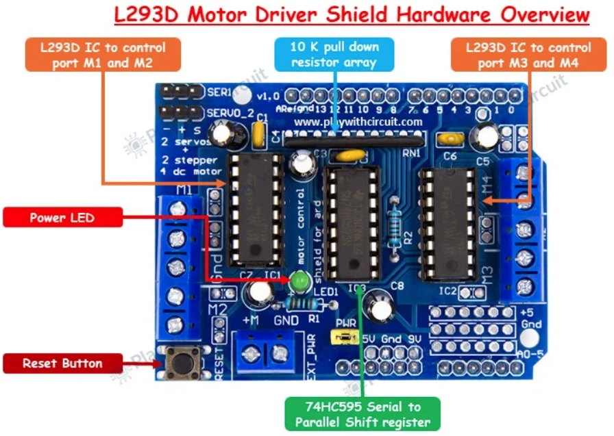
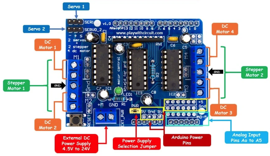
Hardware power engineering guide, power distribution topology, battery sizing, and electrical noise protection for the tracked_bot autonomous robotics platform.
Reference Documentation & Datasheets:
| Main Controller: main_board.md | datasheets/atmega328p.pdf | datasheets/esp8266ex.pdf |
| Motor Driver: motor_shield.md | datasheets/l293.pdf |
| Board Images: images/motor_driver_shield.png | images/motor_driver_shield_pinout.png |
The tracked_bot system separates sensitive digital processing logic from inductive, high-current motor drive loads:
  +--------------------------------------------------------------------------------+
  |                             SYSTEM POWER TOPOLOGY                              |
  +--------------------------------------------------------------------------------+

        [Motor Battery: 2S Li-Ion 7.4V - 8.4V]      [Logic Supply: USB 5V / Power Bank]
                        |                                            |
                        v                                            v
           +--------------------------+                 +--------------------------+
           | EXT_PWR Screw Terminals  |                 | USB Connector / 5V Rail  |
           |  (L293D Motor Shield)    |                 |   (TZT Uno WiFi R3)      |
           +------------+-------------+                 +------------+-------------+
                        |                                            |
        +---------------+---------------+                            |
        |                               |                            |
        v                               v                            v
  +-----------+                   +-----------+                +-----------+
  | L293D IC1 |                   | L293D IC2 |                | ATmega328P| (5V Logic)
  | (M1 & M2) |                   | (M3 & M4) |                +-----+-----+
  +-----+-----+                   +-----+-----+                      |
        |                               |                            v
        |                               v                      +-----------+
        |                     [2x DC Track Motors]             |  ESP8266  | (3.3V LDO)
        |                                                      +-----------+
        v
  [Aux Actuators]

  ==================================================================================
  COMMON GROUND (GND): All power sources share a single low-impedance ground return
The L293D shield provides a 2-pin jumper header labeled PWR (or PWR_JMP) positioned immediately beside the blue EXT_PWR screw terminal block.
[!WARNING] CRITICAL SHORT-CIRCUIT HAZARD: If you connect an external battery or DC power supply to the
EXT_PWRterminal while thePWRjumper is in place, and simultaneously connect the Arduino to a computer via USB or DC barrel jack, the two power supplies are placed directly in parallel. This can destroy the Arduino board, overheat the onboard regulators, and burn out the USB port of your development computer.
| Mode | PWR Jumper State |
Motor Rail Source (EXT_PWR) |
Logic Rail Source (MCU) | Advantages / Drawbacks |
|---|---|---|---|---|
| Topology A: Dual Isolated Supplies (Recommended) | REMOVED (Open) | 2S Li-Ion / LiPo (7.4 V – 8.4 V) on EXT_PWR |
5 V USB Power Bank or separate 5 V buck regulator | Optimal: Complete electrical isolation prevents motor-induced voltage sags from causing MCU brownout resets. |
| Topology B: Shared Single Supply | INSTALLED (Closed) | 7.4 V – 9.0 V Battery connected to EXT_PWR or DC Jack |
Sourced through Arduino onboard LDO from VIN |
Compact: Single battery pack powers everything. Higher risk of brownouts during high-torque skid turns. |
Differential skid-steering tracked vehicles demand sustained current when overcoming mechanical friction during turns. Recommended battery configurations:
| Chemistry | Configuration | Nominal Voltage | Full Charge | Usable Capacity | Recommendation for tracked_bot |
|---|---|---|---|---|---|
| Li-Ion (18650) | 2S1P | 7.4 V | 8.4 V | 2200 – 3000 mAh | Highly Recommended: Excellent energy density, low internal resistance, low sag under load. |
| Li-Po Pack | 2S (7.4V) | 7.4 V | 8.4 V | 1000 – 2200 mAh | Highly Recommended: High continuous discharge rating (20C–30C), compact form factor. |
| NiMH Pack | 6x AA Cells | 7.2 V | 8.4 V | 1800 – 2500 mAh | Good Alternative: Readily available, robust, safe charging characteristics. |
| Alkaline | 6x AA Cells | 9.0 V | 9.6 V | 1500 mAh | Temporary / Testing Only: High internal resistance causes rapid voltage drop under motor load. |
| 9V PP3 Block | 1x 6F22 | 9.0 V | 9.6 V | ~400 mAh | DO NOT USE: Cannot provide motor stall current; collapses within seconds. |
| Subsystem | Component | Typical Idle Current | Active / Operating Current | Peak / Stall Current |
|---|---|---|---|---|
| Controller | ATmega328P (16 MHz, 5V) | 12 mA | 18 mA | 20 mA |
| Wi-Fi Module | ESP8266EX (80 MHz, TX mode) | 35 mA | 80 mA | 170 mA (RF bursts) |
| USB Interface | CH340G Bridge | 10 mA | 12 mA | 15 mA |
| Shift Register | SN74HC595N Logic | < 1 mA | 5 mA | 10 mA |
| Left Motor (M3) | DC Gearmotor (3–6V / 7.4V) | 0 mA | 180 – 350 mA (cruising) | 800 mA – 1.2 A (stall) |
| Right Motor (M4) | DC Gearmotor (3–6V / 7.4V) | 0 mA | 180 – 350 mA (cruising) | 800 mA – 1.2 A (stall) |
| Total System | ~60 mA | ~450 – 800 mA | ~1.8 A – 2.5 A |
[!NOTE] During in-place pivot turns (
MOTION_SPIN_LEFT/MOTION_SPIN_RIGHT), both motors draw maximum torque against the ground resistance. The power supply must be capable of delivering at least 2.0 A peak without dropping below 6.5 V on theEXT_PWRrail.
Brush-type DC motors generate broad-spectrum electromagnetic interference (EMI) and high-voltage back-EMF inductive spikes that can corrupt digital communication or trigger MCU resets.
To quench brush arcing and suppress RF noise:
EXT_PWR:EXT_PWR screw terminals (+ and GND).To prevent deep discharging of Li-Ion/Li-Po batteries (which must never drop below 3.0 V per cell / 6.0 V total for a 2S pack), an analog voltage sensing circuit is connected to analog input A0 (PC0):
  V_BAT (7.4V - 8.4V)
         |
         +----+
              |
             [R1: 30 kΩ]
              |
              +--------> Arduino Pin A0 (ADC0)
              |
             [R2: 10 kΩ]
              |
             GND
\(\text{Division Ratio } K = \frac{R_2}{R_1 + R_2} = \frac{10\,\text{k}\Omega}{30\,\text{k}\Omega + 10\,\text{k}\Omega} = 0.25\)
At full charge ($V_{BAT} = 8.4\,\text{V}$): \(V_{ADC} = 8.4\,\text{V} \times 0.25 = 2.10\,\text{V} \quad (\text{well within the 5.0V ADC reference range})\)
\(V_{BAT} = \frac{\text{ADC\_Value} \times V_{REF}}{1024} \times \frac{R_1 + R_2}{R_2} = \frac{\text{ADC\_Value} \times 5.0\,\text{V}}{1024} \times 4.0\)
A software threshold in the firmware triggers low-battery warnings at $V_{BAT} \le 6.8\,\text{V}$ and emergency motor shutdown at $V_{BAT} \le 6.4\,\text{V}$.
EXT_PWR screw terminals (+ on the left, GND on the right as labeled on the PCB).